The Candela3D-CAD plugin is a companion tool for the main Candela3D program, and it is completely free to users. The Candela3D-CAD plugin offers many practical functions and does not rely on the Candela3D software to run. Some of its tools can significantly enhance our work efficiency, and we highly recommend them.
This article is the first part: graphic element processing. At the end of the article, there are download links and videos demonstrating the installation and uninstallation of the plugin.
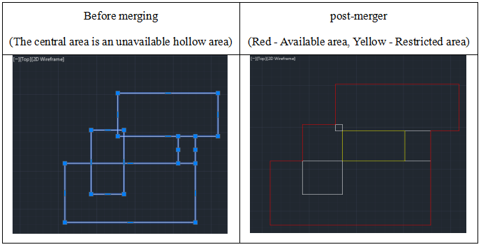
(1) Unionpolyline: The Red line In one cell command, specifically designed for handling a large number of Red line Ranges exported from software such as Ovi and ArcGIS. This command is limited to merging available Areas and cannot select and merge Restricted areas.
After executing this command, the software will display the following interface:

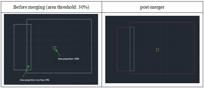
"Area threshold": When the proportion of the intersection area of two areas to the area of the smaller area is below a set threshold, the smaller area is considered disabled, and the union of the two areas is considered an available area.
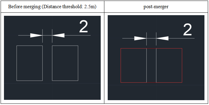
"Distance threshold": For two adjacent areas without intersection, if the distance between them is less than a set value, these two areas will be merged into one available area.
After the merge operation is completed, the software will automatically categorize the merged available areas into the "Candela - Area - Available Range" layer, and categorize the merged restricted areas into the "Candela - Area - Restricted Range" layer.
(2) DeleteSelfconnect: This command is used to remove self-intersecting or overlapping segments in polylines, and it primarily serves the following functions.
① Remove the overlapping segments of a single polyline.
② Remove the self-intersecting parts of polylines.
③ Remove the overlapping segments that are completely contained between polylines (the line width and thickness should be consistent, and the following figure is only for illustration).
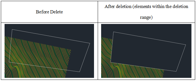
(3) DeletePolyByBound: This command enables users to delete graphical elements within a specified boundary. Users can draw a closed polyline as the boundary and then select the graphical elements that need to be deleted. Next, users can decide whether to retain the graphical elements within the boundary or those outside the boundary, completing the cutting operation of the graphical elements. Compared to the original cutting command in CAD, this command has a faster response speed and is more convenient to operate.
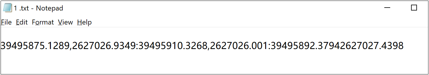
(4) Getxy: This command is designed to batch obtain the center coordinates of selected circles, rectangles, or closed polylines. After execution, the software will automatically generate a *.txt document containing the coordinate information of the selected entities. The X and Y coordinates in the document are separated by commas (,), while the coordinates of different entities are separated by semicolons (;).
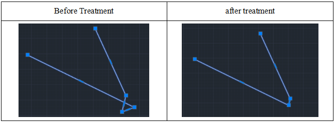
(5) CloseRoadCross: This command is specifically designed to handle polyline objects. If you encounter a line object, you need to first use the PE command to transform it into a polyline (the operation steps are: PE, M, convert the line to a polyline, and then press the ESC key to Quit).
When dealing with road intersections, you can first use the DeleteSelfConnect command for preprocessing.
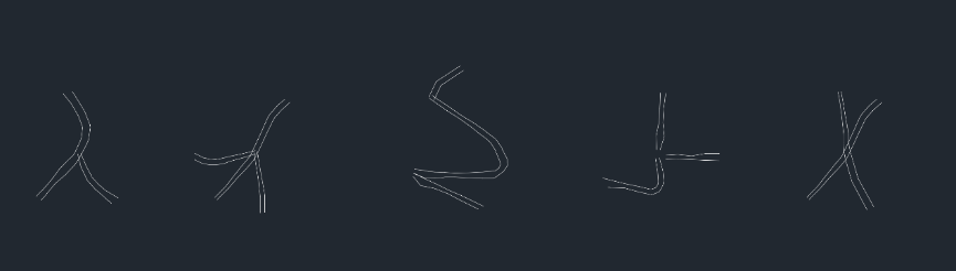
This command primarily addresses the issue of non-closure at road intersections and supports the following types:
After entering the command, choose the polylines to be processed, and the software will pop up a dialog box:
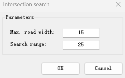
Maximum Road Width: The maximum width of the selected road.
Search Distance: The range should be greater than the maximum Road width and also greater than the length of the connecting line segment required for a closed intersection.
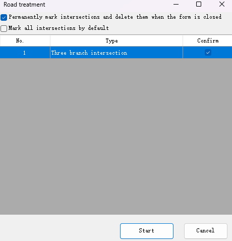
Input the appropriate value in the dialog box, click "OK", and the software will list all instances of unclosed intersections:
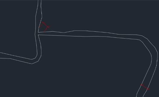
Click "Process Now", and the processed effect is as follows:
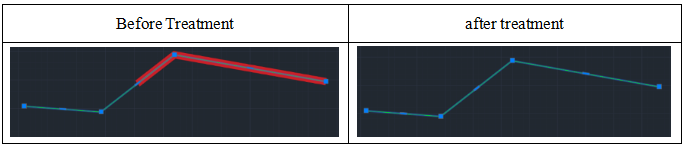
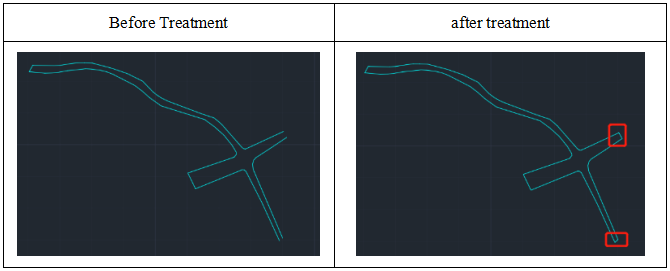
(6) Solving the problem of closed road ends (CloseRoadEnd): This command is only applicable to polyline objects. If a line object is encountered, it must first be converted to a polyline using the PE command (the operation steps are: PE, M, convert the line to a polyline, and then press the ESC key).
When dealing with the issue of closing the end of a road, the DeleteSelfConnect command can be used for preprocessing operations.
This command aims to address the issue of unclosed road ends, and its effect is demonstrated as follows:
(7) pline3trans/pline2trans: This command is specifically designed for polyline transformation, capable of converting 3D or multi-segment 2D polylines into the Standard polyline format.
(8) setplines: This command is used to adjust graphic properties, setting the global line width and thickness of all graphics marked as polylines in the drawing to 0, and uniformly setting the linetype to continuous.
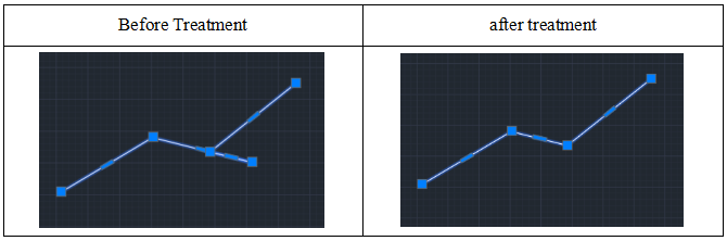
(9) SimplifyPoly: This command is designed to simplify polylines. When the points on a polyline are too dense, the drawing may become bulky and difficult to operate. By applying the simplifyPoly command, you can effectively remove redundant points, thereby reducing the size of the drawing file.
| 1. Plugin download link:https://pan.baidu.com/s/1FVuGkOGeUVTRj5-UDuiqTw?pwd=2si7 2. For the installation, uninstallation, and update of the plugin, please refer to the video below: |
Article Comments(0)