Array layout is a crucial aspect of photovoltaic projects in mountainous regions. In the latest version of our software, we have enhanced the array layout function by introducing multiple configurable parameters, allowing users to more scientifically arrange arrays based on actual construction conditions.
1. Maximum foundation slope
This function is primarily used to prevent the array (partially) from being arranged in areas with drastic terrain changes or excessive slope along the long side of the array. When the array is placed in a certain location, if the absolute value of its base slope exceeds the preset threshold, the software will automatically perform left/right stepping operations until the base slope drops below the preset threshold.
2. Alignment angle
This function is primarily utilized in the design of photovoltaic projects for fish ponds or canals. It allows for specifying a particular edge, drawing an edge, or manually inputting an angle as the alignment direction. After alignment, the front and rear pile positions can be aligned on a straight line, facilitating cable routing on the bridge.

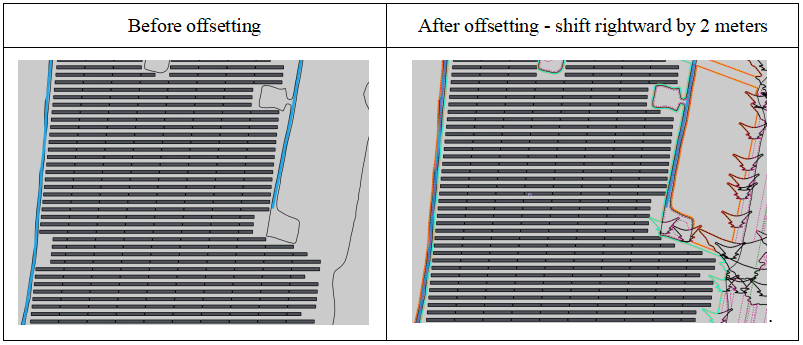
3. Offset adjustment
This feature is primarily applied in the design of photovoltaic projects for fish ponds or canals. It allows for fine adjustments along the long side of the array, moving a specific distance to the left or right. In the layout interface, users can adjust the "left and right side gaps" to achieve an offset effect. However, due to the limitation of the starting row position, this adjustment may result in not only a lateral offset of the array but also a north-south offset.
4. Generate inner hole
This function is primarily used to create prohibited inner holes within the designated layout area, to prevent arrays from being arranged in regions that have not undergone solar radiation analysis and mountain analysis. Furthermore, in cases where there are numerous steep slopes in the terrain, this function can be employed to automatically convert these steep slope areas into inner holes, thereby reducing the workload of terrain map preprocessing.
Users can opt for the automatic generation feature to create internal holes, or choose to manually draw them.

5. Automatically generate horizontal and vertical channel centerlines
This feature is primarily applied to flat land or fish pond projects. When using horizontal and vertical channels, the software will arrange the array and generate channel centerlines based on the "channel spacing" set by the user, facilitating the creation of roads.
"Channel spacing" supports multiple input formats. For example, if you enter 2*4,5,2X6, it indicates that the channel spacing will be 4, 4, 5, 6, and 6 in sequence.
6. Filling and arrangement
This function is primarily applied to filling the layout area with smaller-sized arrays while maintaining the original layout, thereby increasing the installed capacity of the project. When filling, the impact of transformers and their shadows on the layout can be considered.

7. More padding arrays
This function is primarily utilized in ditch projects, allowing for the filling of arrays of various sizes.
By utilizing the aforementioned functions reasonably, one can effectively arrange the array according to the actual situation of the project, thereby ensuring the rationality of the final design.
Article Comments(0)