1. How to increase or decrease the range of the Fille Zone in the 3D modeling interface?
[Teacher Chen]: As shown in Figure 1, the ZONE rectangle is depicted. The size of the rectangle is primarily adjusted by moving the red solid small square with the left mouse button. When the cross arrow of the mouse is placed over the small square, it can be moved. To delete the small square, use the right mouse button. To add a small square, move the mouse to the outer dotted line of the ZONE area and click the left mouse button.
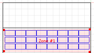
▲Figure 1
2. What is the difference between the meteorology data file exported from Meteonorm meteorological software and the built-in Meteonorm meteorological data in PVsyst?
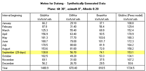
[Teacher Chen]:The data we exported from Meteonorm software typically has a time interval of Hour, and after importing it into PVsyst, we can see from Figure 2 that the Time step in the red solid wireframe is Hour. The meteorological data source file is "DaTong-Shanxi-hour.dat" (exported from Meteonorm software). Figure 3 shows the Meteonorm meteorological database built-in to PVsyst, with a data time step of "month". Figures 4 and 5 show the horizontal plane radiation, scattered radiation, and total radiation on a 30-degree arrays plane for each month of the year. The results show that there is little difference between the total horizontal plane radiation or total radiation on the arrays plane. However, the differences in scattered radiation or direct radiation on the horizontal plane are still very significant. If high accuracy is required for the data, it is recommended to use a meteorological data source with Hour time steps.
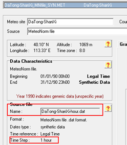
▲Figure 2
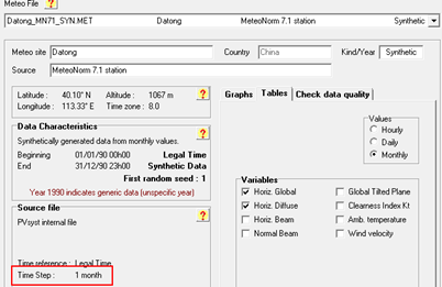
▲Figure 3
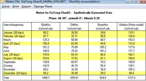
▲Figure 4 Data exported from Meteonorm software
▲Figure 5: Data provided by PVsyst
3. How to quickly create other variables in a project?
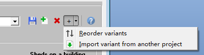
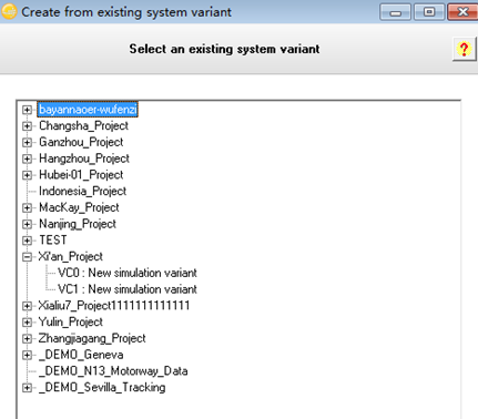
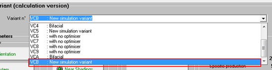
[Teacher Chen]: Generally, a Project can establish multiple Variants, and each Variant can set up a photovoltaic power generation System, but they all use the same Meteorology data. If you want to quickly copy an existing Variant and establish a new System after modifying the parameters, you can use "import variant from another project". As shown in Figure 6, after clicking, a dialog box appears as shown in Figure 7, listing all the existing Project files and corresponding Variants in the current PVsyst software. If the proposed power generation System is similar to a previously established System corresponding to a Variant, we can copy it. After the operation is completed, as shown in Figure 8, the new System will be the 8th Variant. For ease of query, it can be renamed. Then you can modify the 3D Model under this Variant and the System-related parameters, loss values, etc.
▲Figure 6
▲ Figure 7
▲ Figure 8
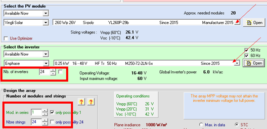
4. How to simulate a household photovoltaic power generation system using a micro-inverter?
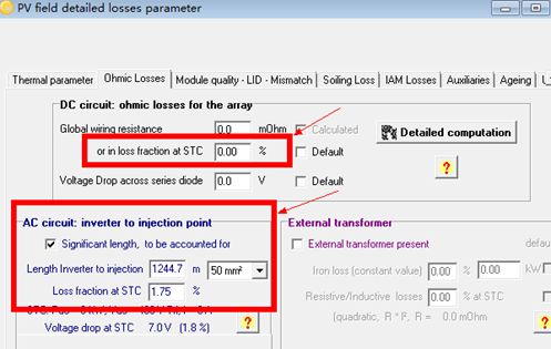
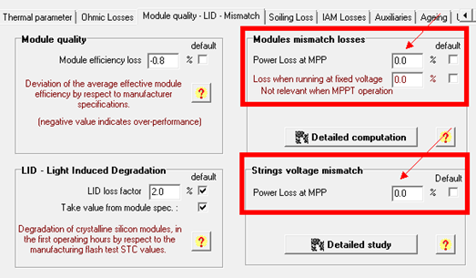
[Teacher Chen]:Taking the Enphase micro-inverter as an example, a PV power generation system comprises 24 PV modules. In the system settings interface, select the Enphase micro-inverter, with one micro-inverter assigned to each module, requiring a total of 24 units. In the string quantity settings, set Mod in series to 1 and change Nbre strings to 24. Since the modules are directly connected to the micro-inverter, the ohmic loss (DC) is zero. Additionally, as the PV modules in the strings independently track the maximum power point, there is no mismatch loss, which can be set to 0 in Figures 10 and 11. After passing through the micro-inverter, the AC output of the modules reaches the low-voltage grid connection point, and the AC ohmic loss can be set to 1.75%-2% (empirical value).
▲ Figure 9
▲Figure 10
▲Figure 11
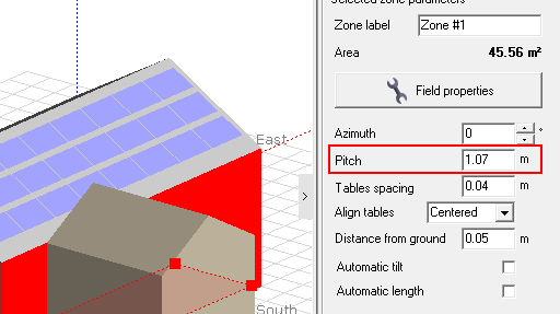
5. In the 3D modeling interface, when using the Table Zones tool, how is the spacing between PV modules or sub-arrays set?
[Teacher Chen]: When using the Table Zones tool, assuming the slope angle of the roof is θ (25°) and the modules are laid flat along the roof, the pitch of the array refers to the spacing on the horizontal plane. Therefore, Pitch = (Module width + Module interval) * cos(θ). If the module size is 1.64m*0.99m, the modules are arranged horizontally, and the module interval is 0.02m, then Pitch = (0.99 + 0.02) * cos(25°). This point requires everyone's special attention.
▲Figure 12
Tip: Interested readers can refer to past articles to search for issues encountered while using PVsyst.
Article Comments(0)