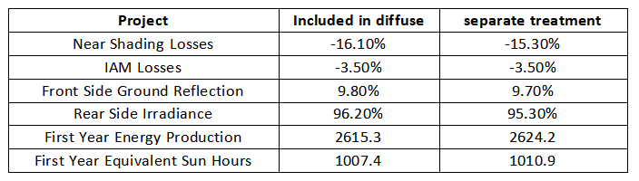
1. Regarding the settings of circumsolar scattering in different versions, what impact do they have on the simulation results?
Answer: In previous PVsyst versions (prior to 6.8), the circumsolar scattering was included in the scattering, whereas versions after 7.0 handle it separately. Especially in application scenarios with large tilts and vertical installations, separate treatment helps improve the accuracy of simulation results.
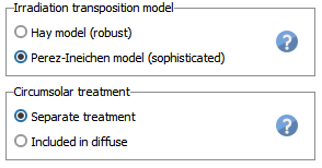
Taking the vertical installation method of a PV module in Northern Europe as an example, the two simulation results of ambient solar radiation included in the scattering and treated separately are shown below. Different settings result in a difference of about 0.34% in hours of production. After separate treatment, the yield is higher.
2. How to set the LID and annual attenuation of PV modules?
Answer: LID stands for Light Induced Degradation, which is related to material aging and annual degradation. These two factors are set separately in the software. According to the manufacturer's warranty, the degradation is linear year by year. Generally, the LID plus the first-year material aging degradation is within the promised warranty. For example, the power degradation of TOPCon in the first year does not exceed 1%, and the annual power degradation does not exceed 0.4%. Many people often set LID to 1%-0.4%=0.6%, which is actually incorrect. LID should refer to the manufacturer's test report.
In the PVsyst simulation phase, if the LID in the first year is 0.3% and the degradation due to material aging is 0.4%, then the power output at the end of the first year will decrease by 0.7% (0.3% + 0.4%). The degradation factor used for the simulation calculation of production is (0.3% LID + 0.4%/2).
Therefore, from a conservative perspective, if the degradation loss in the first year does not exceed 1% and the annual degradation loss is 0.4%, then the LID for the first year can be set to 1%-0.4%/2=0.8%.
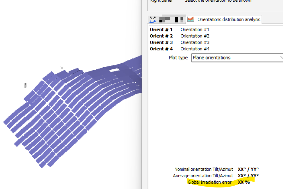
3. When importing a model of a complex terrain array with different orientations, how can we roughly determine the difference in radiation loss caused by orientation deviation?
Answer: Navigate to Near Shadings > "Orientation Management", click on the "Orientation Distribution Analysis" option, and select "Base slope deviation, absolute errors", as shown in the figure below. You can see the deviation loss of XX.XX%.
4. When we were creating the panfile, we encountered the following issue: an error popped up stating "Maximum series resistance (RSMax) = very low, consider increasing the Voc (STC) value." How can we resolve this?
Answer: This is currently a limitation of the PVsyst software regarding the single diode model for PV modules. For STC data of new technologies such as HJT and BC, when the Vmp/Voc ratio is too high (greater than approximately 84% or slightly higher), the single diode model cannot be applied. It is recommended to adjust the electrical parameters of the module and increase the Voc value of STC to enable the application of the model. Since the power generation simulation results always operate near the working voltage Vmpp value of the module string, modifying the Voc value of the module will not have a significant impact on the simulation results.

5. After importing the annual meteorological data, how can we simulate the yield of electricity for a specific day or month?
Answer: Access the User-defined Simulation interface and customize the simulation date. You can simulate the power generation for a specific day or several months.

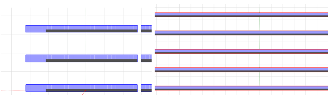
6. What are the main differences between the infinite length fixed (tracking) simulation mode and the establishment of a three-dimensional model?
Answer: The infinite-length fixed tilted plane (tracking rack) mode assumes that the PV Rack is infinitely long on a 2D plane. Therefore, if the front row of the array casts a shadow on the rear row, the lowest row of cells in the PV modules will be shaded. However, if a three-dimensional model is used, as the solar azimuth changes, some areas will not be shaded. Therefore, using the infinite-length mode for simulation results in a higher ratio of shading loss between arrays, while using a three-dimensional model for simulation provides a more accurate ratio of radiation shading loss.
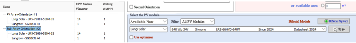
7. Can it simulate Bifacial power generation systems with different orientations?
Answer: Currently, version 8.0 supports the simulation of bifacial power generation systems with different tilt angles in various orientations.


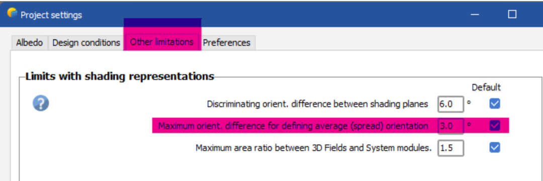
8.The "angle between the field and the average orientation" of the mountain model is "too high".
Answer: To resolve this issue, you need to click on "Project settings", then select "Other limits", and adjust the default angle of 3° to a higher value.
Article Comments(0)