1. Question: Can PVsyst export hourly photovoltaic output?
[Answer from Teacher Chen]: Yes, you can. Open the PVsyst simulation interface and click the "Output File" button, which is "Export file", as shown in Figure 1.
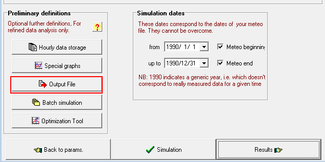
▲Figure 1
After opening, the interface shown in Figure 2 appears. By default, PVsyst does not output any files after simulation, but we can choose to output files and set the relevant formats of the output files, such as date and time format, separator symbol for numerical values, and whether the time span of numerical values is displayed in hours, months, or days. There is a blank option box on the right side, where you can select the corresponding variables according to your needs. The variables from top to bottom in Figure 2 are the total radiation amount of the photovoltaic plane, the maximum power output of the DC-side photovoltaic arrays, and the mismatch loss of the arrays. If there are not enough variables, you can click "Add variable" to add more. After completing the settings operation, you can proceed to the simulation step. After the simulation is completed, a file with a csv suffix format can be obtained, from which the data you need can be found.
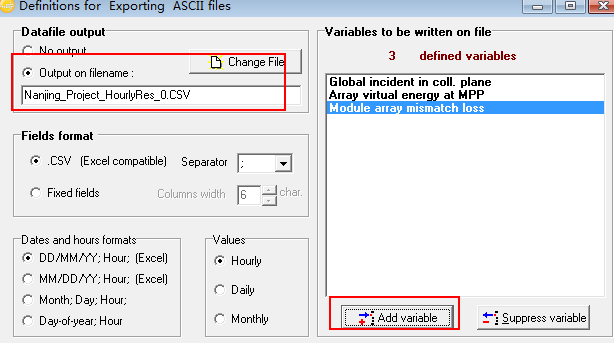
▲Figure 2
2. Question: In the PVsyst 6.64 version, there is a certain drift in the shading curve. What could be the reason for this?
[Teacher Chen's answer]: For the PVsyst 6.64 version, in the 3D modeling real-time shadow demonstration screen, as shown in Figure 3, there is a rectangular obstacle in the middle of the front row of the Array facing directly south. Using Solar Time simulation, with 12 noon as the dividing point, it can be observed that the shadow trajectories on the Winter Solstice morning and afternoon are different. It is understood that this is a minor issue with the program. In the 3D modeling interface, whether it is Solar Time or Legal Time (Beijing Time in China), the simulation is defaulted to Legal Time.
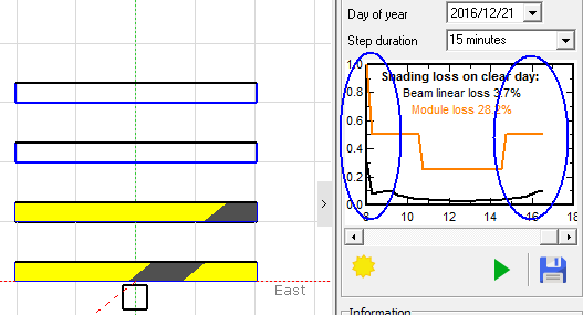
▲Figure 3
However, this does not affect the accuracy of the project's production simulation. From the ISO shading diagram (a graphical representation of the shading coefficient) of the simulation results, the abscissa represents the azimuth of the sun. When the azimuth of the sun is 0, the shading loss values in the morning and afternoon are symmetrical.
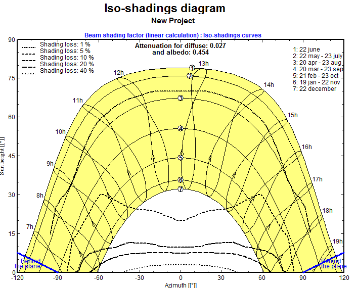
▲Figure 4
3. Are there Bifacial system battery PV modules in the current PVsyst component library File?
[Answer from Teacher Chen]: Currently, PVsyst includes relatively few Bifacial system modules, so for users, it is generally necessary to create their own PAN files for Bifacial system modules. Creating a PAN file for Bifacial system modules is relatively simple, just like for regular modules, except that Bifacial system modules have an additional Bificial Factor. We can open any module, as shown in Figure 5. Find the "Size and Technology" tab of the module, and you can see that the "Bi-Ficial module" is not selected. After selecting it, enter the Bificial Factor (this factor is the ratio of the conversion efficiency of the back side to the front side of the module under STC conditions).
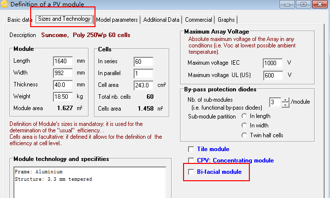
▲Figure 5
4. Is the optimal tilt near the equator close to 0 degrees?
[Teacher Chen's answer]: Import Meteonorm meteorological data from Indonesia (near the equator), and adjust the tilt in the PVsyst tilt and azimuth settings interface. The right side of Figure 6 shows FT (the ratio of inclined surface radiation to horizontal surface radiation), Loss relative to optimization, and photovoltaic plane radiation. When FT is at its maximum, the Loss relative to optimization is 0%, and the total radiation on the inclined surface is at its maximum. The left side of Figure 6 shows that as the tilt angle increases from 0 degrees, the value of FT decreases continuously, with FT being the largest at 0 degrees. Therefore, the optimal tilt angle near the equator can be treated as 0 degrees.
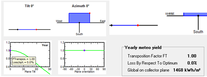
▲Figure 6
5. Regarding the simulation of two tilt angles for winter and summer seasons, how can this error be resolved?
[Answer from Teacher Chen]: For the simulation of two tilt angles in winter and summer, in 3D modeling, the tilt angle for summer is generally used for modeling, as shown in Figure 7, where the summer tilt angle is 20 degrees and the winter tilt angle is 50 degrees. Therefore, the tilt angle of the 3D modeling array needs to be set to 20 degrees, and two different angles cannot be used, otherwise a red English prompt will appear, as shown in Figure 8.
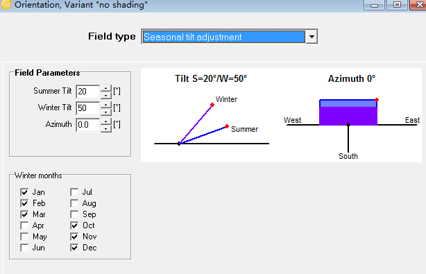
▲Figure 7
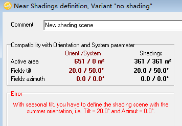
▲Figure 8
6. When accessing the radiation amount on the inclined surface in PVsyst, what does the Albedo factor mean? What value should it be set to?
[Answer from Teacher Chen]: The radiation received by the inclined surface of a PV module mainly consists of three parts: direct solar radiation, scattered radiation from the sky, and reflected radiation from the terrain. The reflected radiation is related to the terrain's albedo (the ratio of reflected radiation to incident radiation). The higher the albedo, the more reflected radiation the PV module receives. By default, PVsyst is set to 0.2. Therefore, when we adjust the tilt using meteorological data to obtain monthly radiation values at different tilts, the default value of 0.2 is also used, as shown in Figure 9. Figure 10 displays the albedo of different materials, which you can adjust and observe the changes in the total radiation on the front side of the photovoltaic panel.
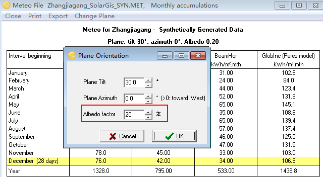
▲Figure 9
Generally, since the proportion of reflected radiation is very small and there is no special application, the default values can be considered. However, for bifacial PV modules, the amount of reflected radiation received on the back side is higher than that on the front side. The actual production varies from site to site, so it is necessary to adjust the ground reflectivity value in the PVsyst software according to the actual situation to achieve higher accuracy.
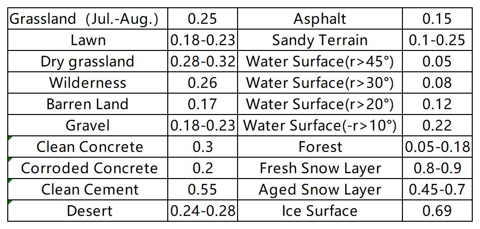
▲Figure 10 Albedo of different Materials
Article Comments(0)