1. Why is there a difference in shading loss when importing terrains of different ranges?
Answer: The software simulates the calculation of shading loss mainly in two types: near shadings and horizon shadings. The former requires modeling, while the latter requires setting the horizon. If a model containing terrain contours and arrays is imported into the 3D modeling, it is generally calculated as near shadings. For terrains with a large area and the farthest point being more than 10 times the diameter of the photovoltaic field, if the ground elevation in the distance is high and may cause shading to the photovoltaic field, the horizon should be set in the software to calculate the horizon shading loss. If not set, the software defaults the horizon shading loss to 0%, which may result in a smaller simulated shading loss.
2. When using a master-slave inverter, what issues should be noted?
Answer: For systems using master-slave inverters, typically two sub-arrays can be established, corresponding to the "master" and "slave" respectively. At the same time, based on the number of strings connected, the maximum allowable current values on the master and slave input sides of the inverter, and the Pnom ratio requirements, the number of strings in parallel and the number of modules in series are set.
3. How to solve the problem of messy codes appearing in the Chinese Report?
Answer: You can download the Arial Unicode MS font and proceed with the installation.
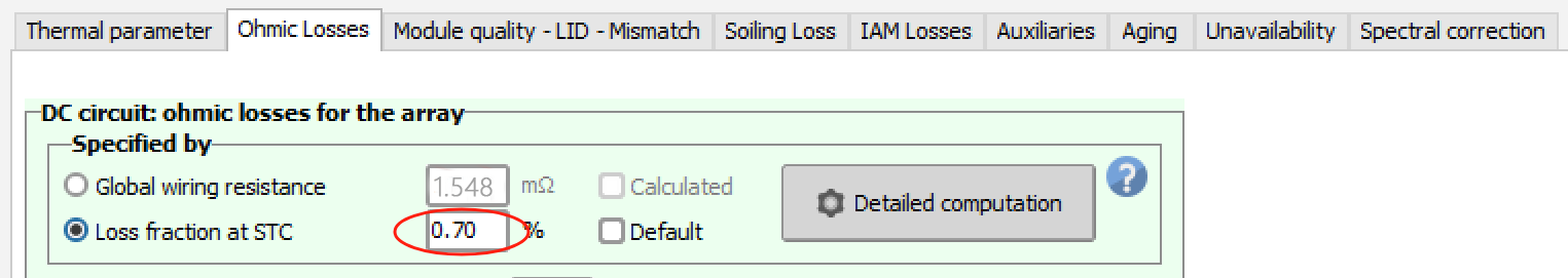
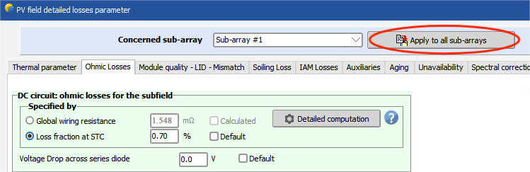
4. Why are there some abnormalities in the simulation results of dc_loss after setting the line loss?
Answer: When multiple sub-arrays are set up in the system, if the line loss ratio is only set in one sub-array and not in the others, it may lead to calculation deviations in ohmic loss (DC) during simulation. You should click "Apply to all sub-arrays" in the top right corner of the cable loss settings interface.
5. Why can't the "Unlimited sheds", "Horizontal axis Unlimited trackers", and the three-dimensional model (Near shadings) array models be used simultaneously?
Answer: The former is generally used for preliminary estimation of the shading loss from the front row to the back row of the array, while the latter calculates the shading loss based on a three-dimensional model (including the self-shading of the array and the shading caused by other obstacles to the array). If both are set, it will result in the shading loss of the array being calculated twice, so only one can be selected.
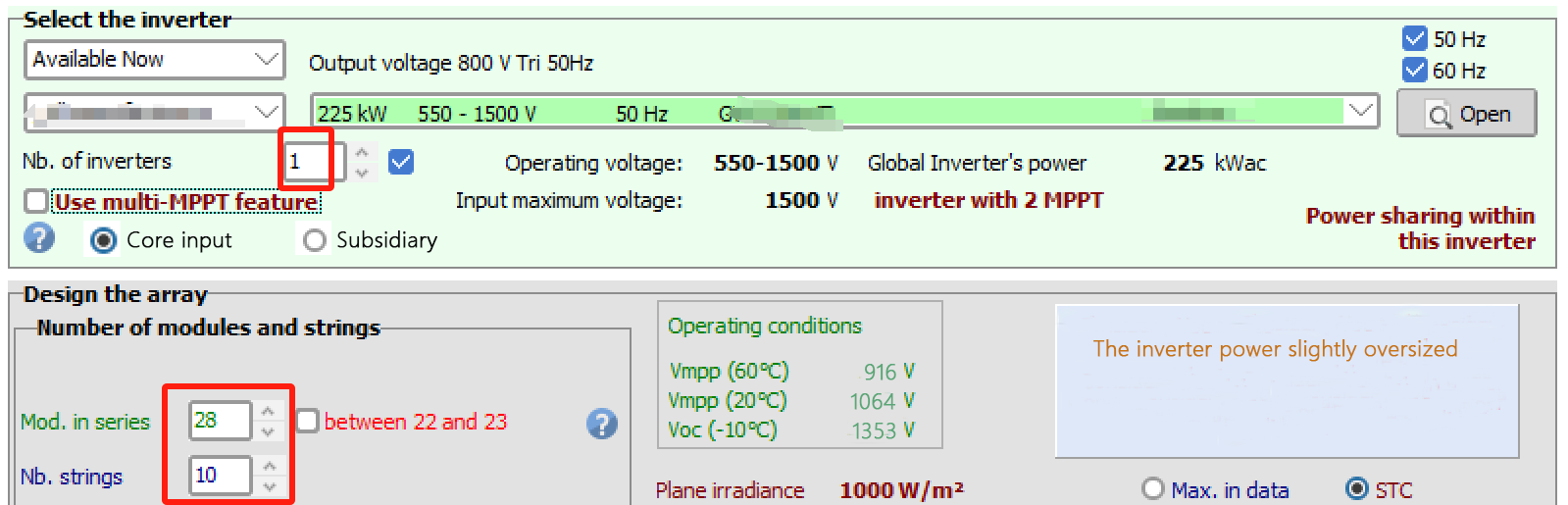
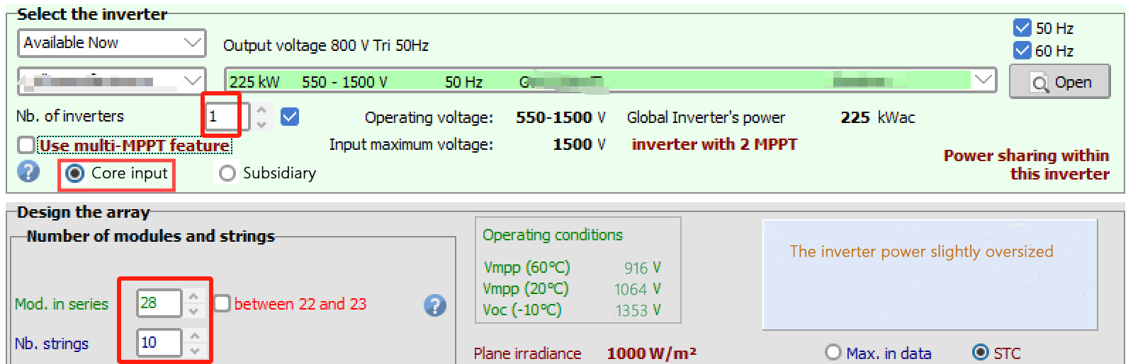
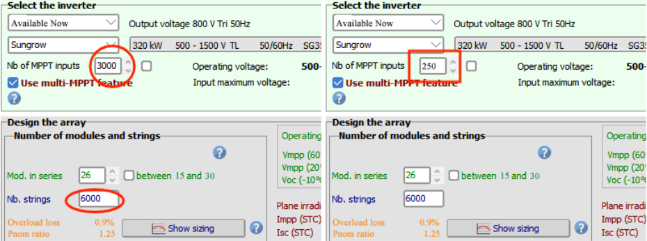
6. What is the difference between selecting and not selecting "Uses multi-MPPT" for a String inverter?
Answer: If the quantity of strings is twice that of MPPTs, there is no difference between the two. If the quantity of strings is an odd multiple of MPPTs, selecting "Uses multi-MPPT" will result in significant differences in simulation results compared to not selecting it. Here is an example to illustrate this.
For example, an 8kW inverter with 2 inputs MPPT is connected to 3 strings, each consisting of 12 250W modules.
After selecting "Uses multi-MPPT", the inverter will allocate 2 inputs to the first MPPT and the remaining 1 input to the second MPPT.
The capacity-matching ratio for the No.1 input MPPT is: 2*12*500/(8000/2)=3, which is relatively high. Therefore, during simulation, the No.1 input MPPT will experience a significant over-matching loss.
The capacity ratio of the second input is: 1*12*500/(8000/2)=1.5, which is smaller than that of the first input, but there may still be over-allocation losses.
② If not selected, the capacity-matching ratio for the first MPPT input is: 2*12*250/(8000*2/3)=1.125, and for the second MPPT input, it is: 1*12*250/(8000*1/3)=1.125. The overall capacity-matching ratio is relatively low, and there is basically no over-matching loss during simulation. Therefore, users should pay attention when using it.
Note: The software version used for the above Q&A is PVsyst 7.2.7
Article Comments(0)