The Candela3D-CAD plugin is a companion tool for the main Candela3D program, and it is completely free to users. The Candela3D-CAD plugin offers many practical functions and does not rely on the Candela3D software to run. Some of its tools can significantly enhance everyone's work efficiency, and we highly recommend them.
The previous article "Candela3D-CAD | Free Use - Practical CAD Plugins (1)" has introduced some of the primitive processing functions. This article is the second part: drawing generation and reverse import. At the end of the article, there are download links, installation, and uninstallation videos for using the plugin.
1. Generate drawing command set
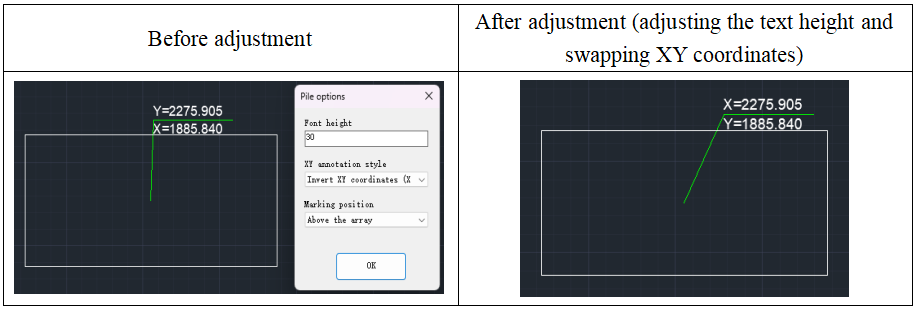
(1) DrawArrayAndTransformerCenter: This command is used to mark the center coordinates of rectangular Pcs. When executing this command, the plugin will automatically identify all rectangular Pcs in the drawing. The user then selects the rectangular Pcs that need to be marked, and the software will automatically mark their center coordinates. Please note that the marked objects are limited to rectangular Pcs. The user can freely set the height of the marking text and choose whether to reverse the XY coordinates or the position of the annotation text. Usually, this command is used for batch marking of center coordinates of arrays or transformers.

(2) changepiletxt: This command is used to adjust the size of Mark text and can swap the X and y-coordinate in the Mark.
2. Reverse import command set
(1) gblock: This command can transform rectangles with the same size in a CAD drawing into a single block (excluding hidden graphics). When using this command, users can input "S" to set the tolerance value for recognizing rectangular frames. The command will recognize and transform parallelograms within the allowable tolerance range into rectangles. However, if the slope of the parallelogram is too large, it is recommended to use the "Convert Polygon to arrays (Poly2block)" command for conversion.
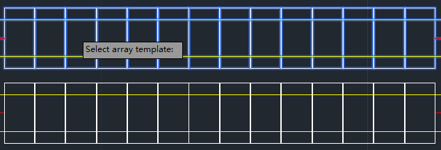
(2) poly2block: This command is capable of transforming a non-block rectangular array into a specified rectangular block.It is used for transforming irregular grid polygons generated for drone flight missions.
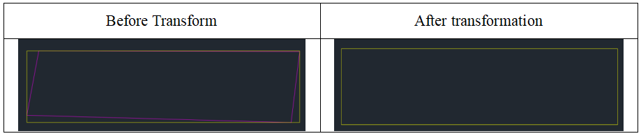
As shown in the table above, in the image before conversion, purple represents the non-rectangular array Pcs to be transformed, and yellow represents the enclosing rectangle of the non-rectangular array Pcs.
When executing this command, the software will complete the following steps in sequence:
① The software will automatically recognize and read the size information of the selected non-rectangular array Pcs (purple), including Length, width, and angle, and based on these Data, construct a virtual outer rectangle (yellow).
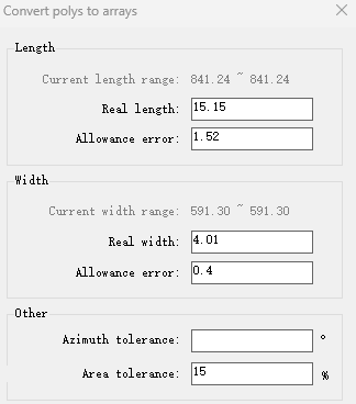
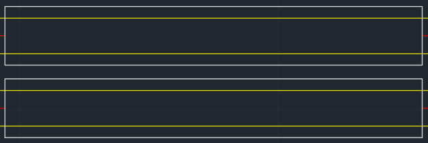
② Users need to enter the actual Length, Width, angle, error, and tolerance values for the rectangular block based on specific requirements. The software will reconstruct the rectangular block based on these Input values. If the newly constructed rectangular block does not meet the preset Standard for either error or tolerance with respect to the outer rectangular (yellow) of the non-rectangular array block, it will not be generated.
③ The newly generated rectangular arrays will maintain consistency with the center coordinates of the enveloping rectangle of non-rectangular arrays. The generated rectangular arrays will be automatically categorized into the "Poly2block" layer.
(3) Module2array: This command is primarily used for drawing layouts with PV modules as the smallest unit, enabling the conversion of rows of adjacent PV modules into a square array.

The specific steps to follow are as follows:
After executing this command, the software will pop up an Operation Prompt. Click the "Confirm" button to start the operation.
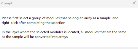
First, select a set of PV modules that form an array as the sample for transformation. After selecting, use the right mouse button to confirm your choice.
The software will automatically identify all PV modules in the same layer as the selected module that match the sample and transform them into an array configuration. You can enter the name of the transformed array block and count the quantity of transformed array blocks. After the transformation is complete, the layer where the original module is located will be automatically hidden, and all transformed arrays will be placed in the "module2array" layer.
| 1. Plugin download link:https://pan.baidu.com/s/1FVuGkOGeUVTRj5-UDuiqTw?pwd=2si7 2. For the installation, uninstallation, and update of plugins, please refer to the video below: |
Article Comments(0)